ETBCA
Item: ETBCA
Fits: Range Rover Sport| '06 - On
LR3 | '05-On
For Range Rover Sport and LR3
1. Remove the panel under the dash on the drivers side of the vehicle, near the brake pedal. There are 2 Phillips Head Screws holding this panel in place. (See Figure #1)

Figure 1.
2. Pull the panel down a little so you can see the Gray connector you will need to connect the Electric Brake Controlled Module. (See Figure #2)
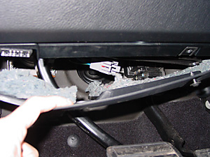
Figure 2.
3. Pull the connector down through the opening where the brake pedal arm extends down toward the floor. (See Figure #3)
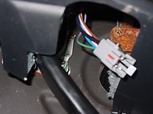
Figure 3.
4. Plug the ETBC Wiring Harness into this plug. (See Figure #4)
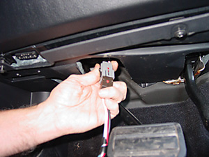
Figure 4.
5. Locate the mounting bracket (for most vehicles it will be the larger bracket) in a location, such that when the Electric Brake Controller Module is in position, it will not block the OBDII (diagnostics) connector. (See Figure # 5) You can either use the sheet metal screws provided to "self-tap" into the plastic of the panel, or you can mark the mounting holes and drill pilot holes with an electric drill fitted with a 1/16 inch drill bit.
Note: A second, smaller, mounting bracket is provided for mounting the controller in a different location of your choosing.
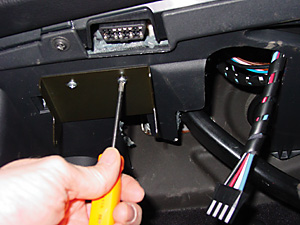
Figure 5.
6. With the bracket securely mounted, plug the ETBC Wiring harness into the back of the Electric Brake Controller Module. (See Figure #6)
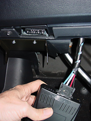
Figure 6.
7. Position the Electric Brake Controller Module in between the "ears"of the mounting bracket and secure with the 2 hex head machine screws. You will need to use a 1/4 inch wrench to tighten the screw on the left side of the module. (See Figures #7 & #8)
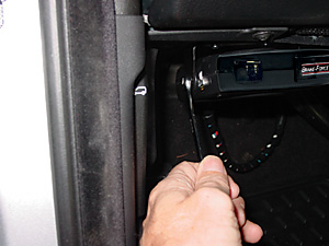
Figure 7.
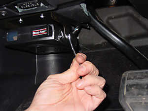
Figure 8.
8. Secure the under dash panel, connect your trailer and test the system. You can also test the operation of the ETBC Module with a Trailer Wiring Simulator like the Tekonsha Trailer Emulator, Part # 54-6562.
Atlantic British Ltd.
M-F, 8am-6pm Eastern
East Coast - Map
6 Enterprise Avenue
Clifton Park, NY 12065 - USA
ClearviewMirrorsUSA.com Is a Division of Atlantic British Ltd.
